Data assimilation
This page provides an overview of assimilating image data into a
modeling and inference workflow. The running example is a set of image
frames frames of a diffusing field on an oval, taken at the times
ts, with square pixels of side pixel_size and the pixels outside the
oval holding NaN.
Projecting image data onto a mesh
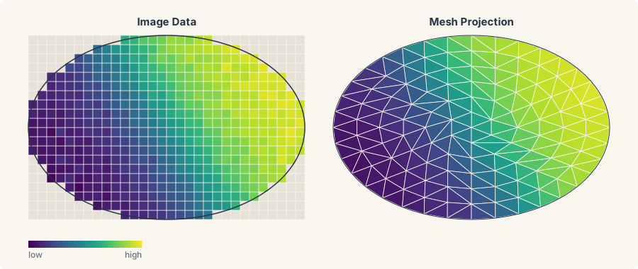
diff-soup provides operators for moving data between image space and
a finite-element mesh. The binary mask of the domain, True on the
oval and False elsewhere, is meshed with mask_to_mesh, a frame is
projected onto the mesh nodes with interpolate_image_to_nodes, and
PixelAveragingOperator maps a nodal field back to the pixels.
from diff_soup.domains.geometry import mask_to_mesh
from diff_soup.inference.data import PixelAveragingOperator, interpolate_image_to_nodes

mask = np.isfinite(frames[0])                                    # True on the oval
mesh = mask_to_mesh(mask, mesh_size=0.05, pixel_size=pixel_size)     # triangles inside the oval
pixel_origin = (pixel_size / 2, pixel_size / 2)                    # the center of pixel [0, 0]
u0 = interpolate_image_to_nodes(frames[0], mesh.points, pixel_origin=pixel_origin,
                                pixel_size=pixel_size, fill=0.0)   # the first frame at the nodes
op = PixelAveragingOperator.from_mesh_and_image(
    mesh.points, mesh.cells, image_shape=mask.shape, pixel_origin=pixel_origin,
    pixel_size=pixel_size, valid_mask=mask)
images = frames[:, mask]                                           # the observed pixels, one row per frame
mask_to_mesh(mask, mesh_size=1.0, pixel_size=1.0, origin=(0.0, 0.0))triangulates the region where the mask isTrue.mesh_size=is the triangle size in physical units,pixel_size=the side of one pixel, andorigin=the physical position of the image corner. It needs the optional dependencygmsh.interpolate_image_to_nodes(image, points, pixel_origin=(0.0, 0.0), pixel_size=1.0, *, fill=None)gives one value per mesh node by interpolating between the pixels around it.pixel_origin=is the center of pixel[0, 0]. A node outside the image takes the nearest pixel.fill=replaces every non-finite pixel before interpolation, so the pixels outside the oval takefill=0.0here; the defaultNonepropagatesNaN.PixelAveragingOperator.from_mesh_and_image(points, cells, image_shape=, pixel_origin=, pixel_size=, valid_mask=None, ele_type="TRI3")builds the observation operator.op.predict(u)returns the pixels a nodal field predicts, in the order ofimages, andop.to_image(pixels)puts them back into an image.UpConvDownOperator.from_mesh_and_image(..., upscale=10)is the operator for a blurred image, with a one-pixel blur applied on a gridupscaletimes finer than the image. It needs matplotlib.
Estimating the initial condition
ds.inference.Experiment(..., initial_state=ds.inference.LearnedInitialState(guess), ...)
fits the initial condition alongside the parameters, with guess the
starting value of the state at the start of the experiment's span. A
bare array stays a fixed state, and ds.inference.FixedInitialState(y0)
is the explicit form. The fitted state reads back from
result.window_states[0], or result.experiments[<id>].window_states[0],
a (1, n_diff) block under single shooting and the first window block
under a latent multishoot; both need optsolve(..., diagnostics=True),
the default. Observed-state windows (Windows.from_data) refuse a
learned state.
Interpolating boundary values
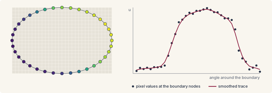
To directly impose Dirichlet boundary conditions from the image data,
we provide extract_boundary_traces and smooth_boundary:
from diff_soup.inference.approx import PiecewiseLinear
from diff_soup.inference.data import extract_boundary_traces, smooth_boundary

boundary = mesh.boundary_nodes()
bc_raw = extract_boundary_traces(frames, mesh.points, boundary,
                                 pixel_origin=pixel_origin, pixel_size=pixel_size)
bc = smooth_boundary(bc_raw, mesh.points, boundary, c_lo=0.0, c_hi=1.0)
trace = PiecewiseLinear(ts, bc)                                    # one column per boundary node
extract_boundary_traces(frames, points, boundary_indices,
  pixel_origin=, pixel_size=, fill_nan=None)
returns one value per frame and boundary node. ANaNpixel takesfill_nan, or the frame's smallest finite value by default.smooth_boundary(bc_raw, points, boundary_indices, method="spline", c_lo=, c_hi=)smooths each frame around the contour and clips it to[c_lo, c_hi].method="spline"fits a periodic smoothing spline with weights1/sigma_eps(sigma_eps=0.01),method="savgol"applies a periodic Savitzky-Golay filter withwindow=7andorder=3, andmethod="raw"only clips.PiecewiseLinear(ts, values)turns the traces into a signal in time, passed asspec.bc.dirichlet(node_indices=boundary, value_fn=trace)(function approximation).
Fitting from the frames
The recipe takes the mesh as its domain and the trace as its boundary
value. The operator's predict goes to ds.inference.Measurement(observe=),
so the fit compares predicted pixels with the frames:
spec = ds.problem("heat_oval")
spec.domain("sheet", mesh)
spec.field("u", mass="differential", scale=1.0)
D = spec.param("D", value=0.1, learnable=True, bounds=(0.01, 2.0))


@spec.equation(writes="u", reads=("u",))
def heat(q):
    return q.p.D * q.ops.laplacian(q.u)


spec.bc.dirichlet("u", node_indices=boundary, value_fn=trace)
problem = spec.build()
y0 = spec.assemble_state({"u": u0})

measurement = ds.inference.Measurement("image", ts, images, observe=op.predict,
                                       weight=1e6)
experiment = ds.inference.Experiment(problem, ds.JIDA(), (float(ts[0]), float(ts[-1])), y0, (measurement,))
result = ds.inference.optsolve(ds.inference.InferenceProblem(experiment, parameters=D))
result[D]                                                          # the fitted diffusivity